Build a Simple Electric Motor
Abstract
When you think of a motor, you may immediately think of a car, but you actually encounter other motors in your home every day. That's right, if you put on clean clothes from the washing machine, ate food from the fridge, or used a fan, you used an electric motor. In this electronics science project, you will make a simple electric motor with two magnets that "talk" to each other. As they interact, they will alternate between "liking" each other (pulling together), and "disliking" each other (pushing away from one another). All that pushing and pulling will create some serious spinning and that is exactly what a motor is, a spinning axle.Summary
Neodymium magnets are very strong. Follow the safety guidelines in the Procedure for working with these magnets.
Objective
Learn how to build a simple electric motor and study how simple changes affect the motor's rotation.
Introduction
What do windshield wipers, CD players, DVD recorders, blenders, ice makers, laptops, and walking toys have in common? They all contain electric motors. In fact, you can walk through your house and find many electric motors hidden in electrical devices, appliances, and toys in every room. The electric motors are not always obvious in devices, and you might need to do some background research about how the devices work to discover where their motors are hidden. Electric motors are an important, and even vital, part of our world today.
But, you may have wondered, just how do those electric motors work? Have you ever played with magnets? If so, you are well on your way to understanding how simple electric motors work. Magnets produce a magnetic field with a north pole and a south pole. If you try to push the north poles of two magnets together, they will not want to come together. Instead, they will repel each other. The same thing happens if you try to push two south poles together. If, however, you bring the north pole of one magnet close to the south pole of another, they will attract each other and stick together. In summary, like poles (north-north or south-south) repel, opposite poles (north-south) attract. The stronger the magnets, the more forceful the attraction / repulsion is between them. As you've probably seen, magnets are typically black, so there is no visible way to tell which end is north and which is south. You can detect the existence of a magnetic field and identify the north/south pole with a compass (which is basically a bar magnet mounted so that it can rotate), as shown in Figure 1, below.
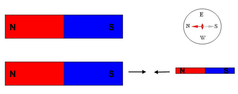
Figure 1. The top part of this diagram shows how the needle of a compass aligns in the presence of a bar magnet, revealing the poles of the magnet. A compass needle is basically a small bar magnet, as shown in the lower diagram. As opposite poles attract, the north pole of the needle will be attracted to the south pole of the magnet. A permanent magnet (further explained below) is represented in this diagram. This method to find the poles of a magnet can also be used to detect the presence and direction of a magnetic field around a temporary magnet (also further explained below).
An electric motor uses the attracting and repelling properties of magnets to create motion. An electric motor contains two magnets; in this science project, you will use a permanent magnet (also called a fixed or static magnet) and a temporary magnet. The temporary magnet is also called an electromagnet. A permanent magnet is surrounded by a magnetic field (a north pole and a south pole) all the time (hence the term "permanent"), but the electromagnet creates a magnetic field (a north pole and a south pole) only when electric current is flowing through a wire (hence the term "temporary"). The strength of the electromagnet's magnetic field can be amplified by increasing the current through the wire, or by forming the wire into multiple loops. Such loops of electrical wire are often called a coil..
To make an electric motor, the electromagnet (the temporary magnet) is placed on an axle so it can spin freely. It is then positioned within the magnetic field of a permanent magnet. This is when things get interesting! When a current is passed through the electromagnet, the resulting temporary magnetic field (made up of a north pole and a south pole) interacts with the permanent magnetic field (made up of a north pole and a south pole) to create attractive and repelling forces. These forces push the electromagnet, which freely spins on its axle, and an electric motor is born. The strength of the permanent magnet and the electromagnet will play a role in the strength of the repelling or attracting forces, and thus, in the speed at which the motor is spinning.
You can actually predict in which direction the coil will be pushed (or in which direction the motor will spin) with Fleming's left-hand rule for motors. Hold your left hand out, as shown in Figure 2 below, with the thumb, pointer, and middle fingers at right angles to each other and imagine arrows at the end of these three fingers. Your pointer finger represents the direction of the magnetic field of the permanent magnet (from north pole, pointing toward your palm, to south pole, pointing away from your finger). Your middle finger represents the direction of the electric current in the wire (which flows trough the wire from the positive terminal of the battery to the negative terminal of the battery). The direction of the force or push on the wire is predicted by the direction in which your thumb is pointing.
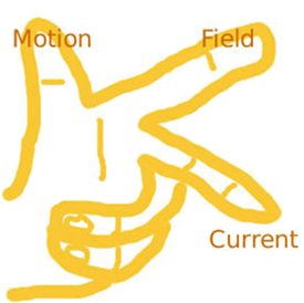
Figure 2. This diagram shows Fleming's left-hand rule for motors: the thumb represents the direction of the force (or push) on the wire, the pointer finger represents the direction of the magnetic field, and middle finger represents the direction of the electric current. Note that all fingers are at right angles to each other.
Can you apply this rule to the current in the short piece of wire shown in Figure 3, below? Hold your left hand with your middle finger pointing to the right (the direction of the current), your pointer finger pointing at a right angle to the middle finger (direction of the magnetic field, represented by the black dotted arrows in Figure 3), and your thumb at a right angle with respect to your middle and pointer fingers. Is your thumb pointing up? It should be, as in this configuration, where the wire will be pushed upward.
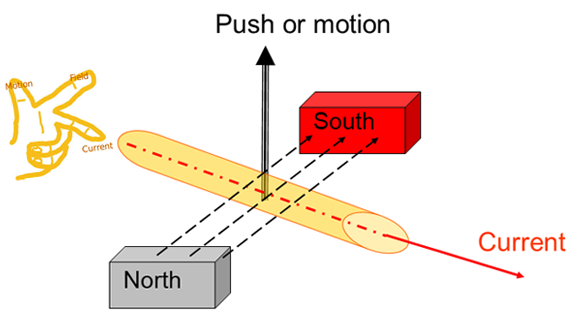
Figure 3. Diagram showing the direction in which a current-carrying wire (electromagnet) will be pushed when placed in a permanent magnetic field, based on Fleming's left-hand rule for motors. The direction of the permanent magnetic field—from north pole to south pole—is represented by black dotted arrows in this diagram.
Knowing how a current-carrying wire moves, what would happen if the wire was bent into a loop? Figure 4, below, will help you find out. You can (in your imagination) break the loop up into individual segments of straight wire, analyze those using Fleming's left-hand rule, and use this to determine which way the loop will move. Figure 4 shows the loop broken up into a wire close to the south pole and one close to the north pole. Using Fleming's left-hand rule shows that the segment closer to the south pole is pushed up, and the segment closer to the north pole is pushed down. In other words, the two sides of the loop are pushed in opposite directions, right? When the wire loop is placed on an axle, these pushes in opposite directions cause it to spin. (Note, no force or push is created when the magnetic field and the current run parallel to each other.)
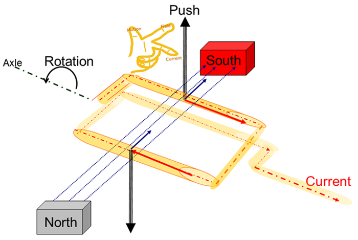
Figure 4. Diagram showing the direction in which a current-carrying wire loop (electromagnet) will be pushed when placed in a permanent magnetic field, based on Fleming's left-hand rule for motors. The direction of the permanent magnetic field—from north pole to south pole—is represented by black dotted arrows in this diagram.
The electromagnet is most often a coil, or a bundle of loops. Because all loops of wire are parallel, each loop will get the same push. Adding up all those pushes, or motions, creates the nice spinning movement of a motor.
If you are a little frustrated that you do not understand exactly how Fleming's left-hand rule works, don't worry! Just keep it in mind as you make the motor, study it, and try to understand the physics behind it again once you have seen the motor running.
To make a motor, the electromagnet must spin in full circles. Let us get a little more practice with Fleming's left-hand rule of motors and predict the direction of motion for different positions of a current-carrying coil placed in a permanent magnetic field and see what happens. Scientists use schematic drawings (diagrams) of electric circuits. Two such drawings can be found in Figure 5, below. They both represent a battery-powered current-carrying coil (or electromagnet) placed in a magnetic field. Drawing B results from Drawing A, as the electromagnet rotates over 180 degrees. Use Fleming's left-hand rule to predict in which direction the coil will turn for Drawing A and for Drawing B.
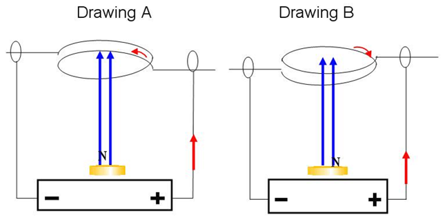
Figure 5. Schematic drawings are used to predict in which direction a current-carrying coil will move when placed in a permanent magnetic field. The blue arrows indicate the magnetic field (away from the north pole), and the red arrows indicate the direction of the current (positive terminal to negative terminal of the battery). The motion of the coil can be determined using Fleming's left-hand rule for motors.
Did you predict that the direction of rotation in Drawing A would be opposite to the direction in Drawing B? That is correct. These opposite forces will make the electromagnet flip forward and back, but never let it make a full turn. To create a motor, the electromagnet needs to rotate continuously, either clockwise or counterclockwise. Before you read on, can you think of a way to make the electromagnet spin around continuously?
There are actually several ways to make the electromagnet placed in a permanent magnetic field spin. The solution applied in this science project uses Newton's first law of motion , which states that an object in motion remains in motion unless acted upon by an outside force. This means that when the electromagnet is spinning, it will continue to coast through a rotation unless something stops it. As discussed above, if current is always flowing through the wire, the resulting pushes will oppose each other, and the coil will bounce back and forth, but not spin continuously. However, if we can make the current flow only half of the time, all the pushes are in the same direction. This means the coil is actively pushed one-half of each rotation while current is flowing, and "coasts" through the next half while no current is flowing, until it comes around and receives the next push. This allows the motor to spin continuously. If this is your first experience with electrical circuits, it is important to remember that electrical current always needs a complete path in which to flow; in this case, from the positive to the negative terminal of the battery. If there is a gap in the circuit (for example, a disconnected or broken wire), the current will stop flowing.
This science project walks you through the process of creating your own simple electric motor. You will start by creating an electromagnet suitable for the motor. This temporary magnet will then be placed in a permanent magnetic field and off it goes!
Terms and Concepts
- Electric motor
- Magnet
- Magnetic field
- North pole
- South pole
- Repel
- Attract
- Permanent or static magnet
- Temporary magnet
- Electromagnet
- Electric current
- Axle
- Fleming's left-hand rule for motors
- Beakman's motor
- Electric circuit
- Electrically insulating
Questions
- How many electric motors can you count throughout your home?
- What happens when two magnets get close together?
- What is the difference between a permanent magnet and a temporary magnet?
- How do you create a temporary magnet (an electromagnet) and what will determine its strength?
- How can you detect a magnetic field?
- What are the parts of a simple electric motor? Which of those parts can spin and what causes the spinning?
- What does Fleming's left-hand rule for motors explain?
- How can you make the electromagnet spin in full circles?
- What will make the motor spin faster or slower?
Bibliography
These sources show the parts of a simple electric motor, how they work, and where to find them:
- Brain, M. (2008). How electric motors work. Retrieved July 26, 2013.
- Woodford, C. (2012, April 12). Electric motors. Retrieved July 26, 2013.
This source provides information on Fleming's left-hand rule for motors:
- Pass My Exams. (2012). The Motor Effect. Retrieved July 26, 2013.
This source provides information on how Beakman's motors work:
- Palmer, C. (2011, July 20). Beakman's Electric Motor: How It Works. Retrieved July 26, 2013.
Materials and Equipment
Recommended Project Supplies
These specialty items can be purchased from our partner Home Science Tools:
- Electric Motor Generator Kit (1). You will need these items from the kit:
- Magnet wire, enamel-coated, approximately 50 inches [120 cm]. This quantity allows for recoiling a second coil if needed.
- Jumbo paper clips (2), metallic, 1½–2 inches [2.6 cm] long
- Sandpaper, fine-grit
- Neodymium magnets (3), 1/4 inch [0.6 cm] diameter
- Compass (1)
- Booklet
You will also need to gather these items:
- A dowel or other cylinder, 1/2 inch [1.3 cm] in diameter, such as the cap from a large felt-tip marker. As an alternative, tape four pencils that have free ends (no erasers) together (such as colored pencils), as explained in the Procedure
- Ruler or measuring tape
- Scissors
- Piece of cardboard, 2 x 3 inches [5 x 8 cm]
- Battery, C cell (2); though you may only use one, it's a good idea to have a second one on hand, as it is likely you will drain the first while tinkering.
- Tape (electrical tape or masking tape works best)
- Lab notebook
Experimental Procedure
Building the Electromagnet
- If you have a cylinder with a diameter of about 1/2 inch (1.3 cm), you can skip this step. If you are using pencils, tape four of them in a bundle, with the tips on one end and the free ends on the other, as shown in Figure 6, below.

Figure 6. A felt-tip marker cap (left) or four pencils taped together (right) can be used to help neatly coil magnetic wire.
- From one end of the magnet wire, measure about 1.6 inches (4 cm), and from that point onward, wind the magnet wire 10½ times around the cylinder or taped pencils. Cut the magnet wire with the scissors, leaving about 1.6 inches (4 cm) free (uncoiled) at each end.
- The magnet wire must be neatly and evenly coiled. If it is not, the weight may not be evenly distributed, making it difficult for the electromagnet coil to rotate in the final motor setup. Try to ensure the loops are touching each other, always parallel to one another, as shown in Figure 7, below.
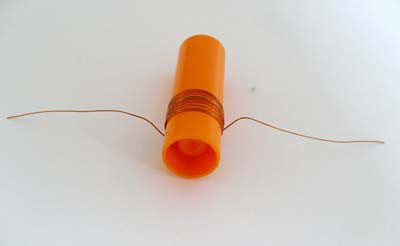
Figure 7. A coil (or electromagnet) is created by coiling magnetic wire 10½ times neatly around a cylinder. Note 1.6 inches (4 cm) of wire is left free on each end to create the axles.
- Carefully slide the loops of magnet wire off the pencils or cylinder. Your coil might look circular or square, as shown in Figure 8, below. How to hold the loops together is explained in step 4.
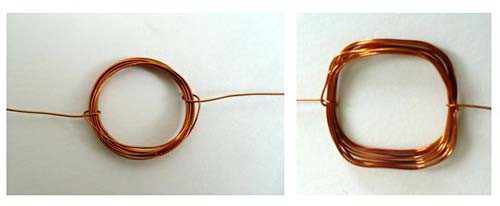
Figure 8. Two examples of neatly coiled wire, each creating an electromagnet.
- Keep the loops bunched together to form a tight coil:
- Thread each free end of the magnet wire through the loops of coil in the 3 o'clock and 9 o'clock positions, as shown in Figure 9, below. If desired, you can knot the magnet wire to help the coils stay tightly bunched.
- The free ends of the magnet wire should form a straight imaginary line through the coil (the imaginary line connects the 3 o'clock and 9 o'clock positions and runs further along the free ends). The free ends will be the axle upon which your electromagnet (the coiled loops of magnet wire) spins.
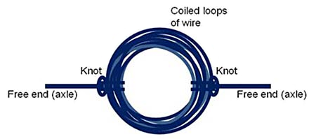
Figure 9. Drawing showing how the coil (the electromagnet) and the axle that it spins on look when formed. Note how the two axles lie in an imaginary straight line across the middle of the coil.
- The magnetic wire is protected with electrically insulating enamel coating. As explained in the Technical Note, below, this electrical insulation needs to be removed from the ends of the axles to create electrical contact between the axle and the axle support. It is important to be thorough about stripping off the insulation. Practice stripping off the enamel insulation on a practice piece of wire before doing it on either the right or left axle.
- To strip only the top half of the insulation off the end of a practice wire piece:
- Lay one end of the wire on a piece of cardboard (to protect the table underneath) at the edge of a table or counter. Hold the other end of the wire in your hand. Figure 10, below, shows how you should hold the coil when stripping the top half of the insulation of the axle.
- Rub the sandpaper over the wire to remove the top half of the insulating material from the magnetic wire.
- The insulating coating is removed when you can see the copper wire underneath.
- To strip all the insulation from the end of a practice wire piece:
- Fold the piece of sandpaper in half, with the rough sides facing each other, to make a "sandpaper sandwich."
- Put the end of the magnet wire that you want to strip inside the sandpaper sandwich, as shown in Figure 11, below. While softly pressing the sandpaper sandwich together, gently rub it over the wire, back and forth.
- Give the wire a quarter turn and rub some more to remove the coating on all sides of the wire.
- The wire is stripped when you can see the copper wire underneath.
- Be careful not to press too hard when rubbing or the wire could break.
- To strip only the top half of the insulation off the end of a practice wire piece:
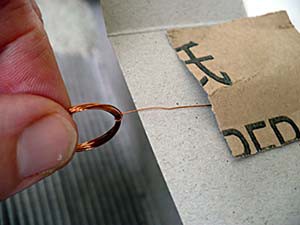
Figure 10. Illustration of how to hold the coil to strip the top half of the axle coating. The cardboard is placed at the edge of a table. The end of the wire is place on the cardboard, holding the coil in an upright position (perpendicular to the floor). The coating is removed by rubbing sandpaper over it.
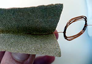
Figure 11. Illustration of how to strip all insulating coating from the left axle.
- Now that you are done practicing, carefully strip the insulating material off the top half of the end of the right axle, as shown in Figure 12, below. Note: This is an important step, so try to be precise!
- An easy way to strip off the insulating material is to hold the coil between your thumb and forefinger so it is standing upright (perpendicular to the floor) and then hold the coil off to one side of a table, as shown above in Figure 10.
- Strip the coating by rubbing the sandpaper over the axle, as you practiced in step 4.a. Note : Only the end of the axle needs coating to be removed. The first centimeter (3/8 inch) of the axle (closest to the coil) does not need to be sanded.
- Do try to remove all the coating on the top side of the wire. You should be able to see the bare copper wire.
- Flip the coil around and sand the end of the left axle. On this side (the left axle), remove all the coating, as shown in Figure 12, below. Note: This step is important as well, so try to be accurate.
- Strip the coating by rubbing the sandpaper over the axle, as you practiced in step 4.b. Note: Only the end of the axle needs coating to be removed. The first centimeter (3/8 inch) of the axle (closest to the coil) does not need to be sanded.
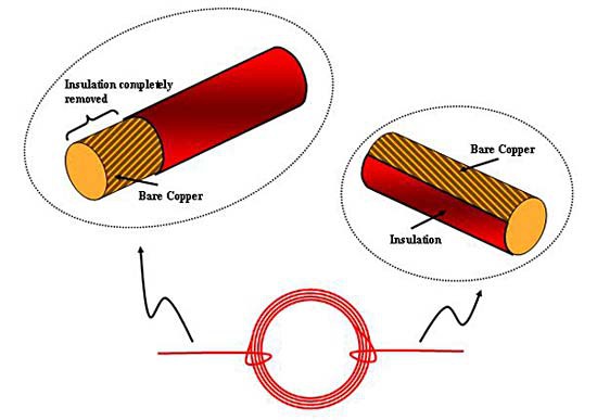
Figure 12. The top part of this drawing shows how the axles should be stripped: on the right axle, only the top half of the coating should be removed; on the left axle, all the coating should be removed.
Why do we strip the wire this way? Remember that stripping the insulation allows electrical contact so electrical current will flow. Stripping off the top half of the insulating material on the right axle will provide a period of time when current can flow through the coil to create a temporary magnetic field and a period of time when current cannot flow, so no temporary magnetic field is created.
- When the bare copper of the axle is rotated downward, bare copper will be touching the axle supports, and current will flow to the coil. As soon as current flows through the coil, it becomes an electromagnet, creating a temporary magnetic field. The temporary magnetic field will interact with the permanent magnetic field and give the wire a push.
- When the bare copper is rotated upward, insulated copper will be touching the axle supports, and no current will flow to the coil. There will not be a temporary magnetic field. According to Newton's first law of motion (referenced in the Background Information), the coil will keep moving the way it moved before, because no force is stopping it.
- As soon as the bare copper of the axle is rotated down again, current will flow and the coil will get a new push, making it rotate around and around.
So far, you have built the electromagnet. Now you will build the base and hook it up to the battery so that current can flow through the coil.
Building the Axle Supports
- Bend the inner part of each of your two paperclips open to create the structure, as shown in Figure 13, below. Basically, gently lift the shorter section of the paperclip and slowly move it upward (like a clock hand), counterclockwise over the longer piece, until it is in the 12 o'clock position, with the original longer section still in the 6 o'clock position. The paperclip should now look like an elongated number 3 with a tiny, more or less circular, hole in the middle.
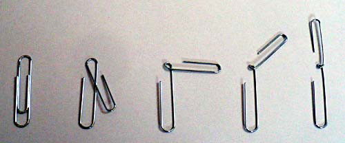
Figure 13. Step-by-step illustration of how to bend a paperclip (shown on the left) to create the axle support (on the right).
- Use tape to secure one paperclip to the positive end of the C cell battery, as follows. Note that electrical contact is created between the axle support (paperclip) and the battery terminal.
- Stand the battery upright so the positive side faces up.
- Place the bigger loop of one paperclip such that the metal goes around the bump on the positive side of the battery, as shown in Figure 14, below.
- Secure the paperclip with tape, as shown in Figure 14. Do not cut the tape yet.
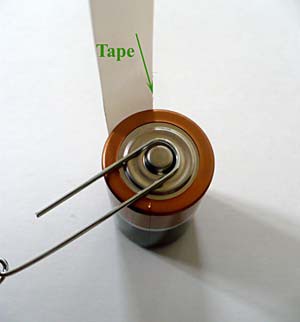
Figure 14. Secure the paperclip to the battery with tape to build the axle support. The green arrow indicates it is about to be folded over to cover the paperclip and battery top. Note that electrical contact is created between the battery and the axle support (paperclip).
- Secure the other paperclip to the negative end of the C cell battery. Note, also on this side, that electrical contact is created between the axle support (paperclip) and the battery terminal.
- Turn the battery over so it rests on its positive side, the side to which a paperclip is already attached.
- Place the bigger loop of the second paperclip such that the metal lies on the side of the bump on the negative side of the battery, as shown in Figure 15, below. Be sure to align the second paperclip with the first, both pointing away from the battery in the same direction.
- Use the tape to hold the paperclip in place.
- If needed, to create a secured structure, you can wrap the tape around the battery a second time before cutting it.
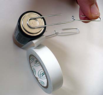
Figure 15. Secure the second paperclip to the battery with tape to complete the axle support.
- Your finished support system can be balanced in the fold of an opened book (such as the booklet that came with your Science Buddies kit), as shown in Figure 16, below.
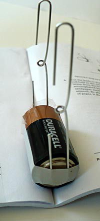
Figure 16. An opened booklet balances the support of the motor well.
Building the Electric Motor
Time to put it all together! Let Figure 17, below, be your guide.
- Open the booklet that comes with the kit (or any other book) and balance your battery and its attached axle supports in the fold of the booklet, axle support facing up, as can be seen in Figure 17.
- Place three small cylindrical neodymium magnets, one on top of the other, on the battery in the middle between the two axle supports.
- Insert each axle end into a loop of the axle support. Your motor might well start running right away! Wow! Great job!
- In case your motor needs some fine-tuning:
- Adjust the axle supports so the axle is horizontal.
- Give the coil a few turns to make sure it can spin freely and does not rub against the magnet.
- Turn your coil 180 degrees, as maybe the uncoated side of the axle was facing up, not touching the axle support. Contact of the bare wire with the axle support will create an electrical connection and allow current to flow.
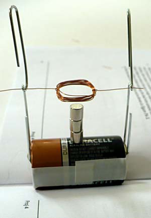
Figure 17. Picture of a finished electrical motor, showing the different parts of the motor and how to combine them together.
- In case your motor is still not running, try the following troubleshooting tips:
- Gently flip the electromagnet (the wire coil) back and forth to make sure that it can easily rotate 360 degrees. If it cannot, it is probably because the weight is not distributed evenly, and you will need to tinker with the loops of the coil (or even re-coil the magnet wire) until it can rotate smoothly.
- Evaluate if current is flowing through your electromagnet. Remove the permanent magnets, bring the compass close to your coil, and see if the compass needle moves. Shake your compass and see if it will align again. If it does, go to step c. If it does not, rotate your coil 180 degrees and evaluate if current is flowing in that position. If it is, go to step c. If it is not, there is no current flowing through your electromagnet. Try these tips:
- Make sure no insulating material is left on the stripped parts of the axles that are in contact with the axle support. If you have a magnifying glass handy, it might help you evaluate if coating is left on the stripped parts. Small leftover pieces of coating can inhibit current from flowing through the electromagnet. Remove leftover coating where needed and try again.
- Make sure your battery is fresh. This motor—even one that is not rotating—will drain a battery quickly as soon as current can flow.
- To evaluate your battery without a multimeter, use another paperclip to create an electrical connection between the two supports, as shown in Figure 18, below. Unfold the paperclip so it can span the distance between the 2 axle supports. Use it to connect the axle supports for a short time to evaluate with a compass if current flows through that connection, as you did in step 4.b. of this section. Important: Do not leave this connection on for long; it will quickly drain your battery!
- Check that all electrical connections are tight as the current can only flow if there is a complete path (a closed circuit); in this case, from the positive to the negative terminal of the battery. Make loose connections tight and try again. Figure 19, below, indicates the electrical connections in your motor.
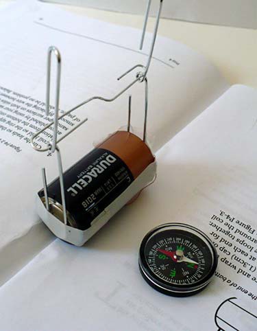
Figure 18. A paperclip is used to create a temporary electrical connection between the axle supports in order to evaluate, with a compass, if the battery is still fresh. Remember to remove the connection as soon as your compass indicates current is flowing; if you do not, it will quickly drain the battery.
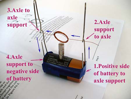
Figure 19. Figure of the finished motor indicating the electrical connections. The direction of the current is indicated by blue arrows. Starting from the positive side of the battery, electrical connection 1 allows current to flow from the positive side of the battery to the axle support. Electrical connection 2 (axle support with axle) allows current to flow to the electromagnet (coil). In electrical connection 3, the electrical loop is closed if the other axle makes an electrical connection with the axle support. Since only half of the insulation of that axle was removed, this electrical connection only exists half of the period of time. Electrical connection 4 connects the axle support to the negative side of the battery.
- If current is flowing through the electromagnet, but the motor is still not running, try the following tips:
- Make sure the insulation is stripped from only the top half of the right axle. If you strip too much, forces in opposite directions will cause the motor to fail. If you have stripped off too much of the insulation from the right axle of the coil, create a new electromagnet with a new piece of magnet wire (repeat steps 2–6 in the "Building the Electromagnet" section), and try to strip only the top half of the wire on the right axle more carefully. Try the motor with the new electromagnet.
- Try repositioning the permanent magnets slightly. There is often a "sweet spot" for the permanent magnets where the motor works the best. You can also try some of the other permanent magnets that come with the kit.
- If current is flowing (regardless of the fact that your motor isn't turning), the magnetic wire will feel warm, or even hot, after it has been connected to the source (battery) for a short period of time. You might even smell a burning smell. Give the axle a small push so the coil shifts and falls out of the support. Let it cool down for a moment before testing again.
- To turn the motor off, shift the axle of the coil to one side until it falls out of the support. To turn the motor on, put the axle back in place.
Comparing Different Electric Motors
Now that you have assembled a running electric motor, it is time to compare different configurations.
Study the direction of spin
- Copy the following data table in your lab notebook. It will be used to record your findings.
|
Strength of the Permanent Magnetic Field (Number of magnets used) |
Direction of the Permanent Magnetic Field (Pole closest to the electromagnet) |
Spinning Direction (Clockwise / counterclockwise when looking at the positive side of the battery) |
|---|---|---|
| 3 magnets | N | |
| 3 magnets | S | |
| 3 magnets | N / motor upside-down | |
| 3 magnets | S / motor upside-down |
- Prepare your motor with two or three small cylindrical neodymium magnets. Choose the configuration that makes your motor run well, but not too fast. Observing the direction on a fast-running motor can be tricky.
- With your compass, determine which pole of your magnet is facing the electromagnet, as shown in Figure 20. If the red (north) end of the needle is pointing up, as shown in the figure, then the north end of the permanent magnet (and thus the magnetic field direction) is also facing up, and vice versa. Study how the current will flow through the wire (from the positive to negative side of the battery) and use Fleming's left-hand ruleto determine in which direction the motor will spin when turned on. Record your predictions in your lab notebook.
- Place your electromagnet (coil) in place.
- Write down the direction the coil is spinning in your lab notebook, when viewing the motor from the positive side of the battery, which is the same point of view as shown in Figure 20, below.
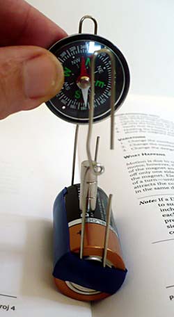
Figure 20. Figure showing how to determine the magnetic pole of the permanent magnet facing the electromagnet. If the red (north) end of the needle is pointing up, as shown in the figure, then the north end of the permanent magnet (and thus the magnetic field direction) is also facing up, and vice versa. This figure also shows from which angle to look at the motor when observing its direction of spin.
- Turn your motor upside-down (pick up the battery and hold it upside-down so the axle support is facing down). You can, but do not need, to stop the motor to do this. Note the direction the coil is spinning in your lab notebook. Be sure that you are still looking at the positive side of the battery.
- Switch the motor off.
- Record all your observations in the data table in your lab notebook.
- Flip the magnets over so the other pole faces up toward the electromagnet and repeat steps 3–8.
- Do your observations agree with Fleming's left-hand rule for motors?
Study the effect of different strengths of permanent magnets
- Copy the following data table in your lab notebook. It will be used to record your findings.
|
Strength of Permanent Magnetic Field (Number of magnets used) |
Spinning Speed (Not running / wiggling back and forth/ running slow / running fast ) |
Spinning Direction (Clockwise / counterclockwise when looking at the positive side of the battery) |
|---|---|---|
| 1 magnet | ||
| 2 magnets | ||
| 3 magnets |
Table 2. Sample data table in which to record observations of the effect of different strengths of the permanent magnet on the motor's spinning speed and spinning direction.
- Prepare your motor with one small cylindrical neodymium magnet place in the center of the battery. Note you can choose to use your motor upside-down or standing in the fold of a book, but do stick with the chosen direction for steps 12–19.
- Start your motor again by placing the electromagnet (coil) in place.
- Observe: is your motor running? If so, is it turning slowly, fast, or somewhere in between?
- Write down your observations in the data table.
- Add a small cylindrical neodymium magnet on top of the other, increasing the strength of the permanent magnetic field. If your motor was running, try not to stop your motor when you add the magnet. Magnets attract each other (or repel depending on which side you bring close). Bringing the magnet close to the motor is often enough to get the magnets to stack one on top of the other.
- Observe the effect of adding an extra magnet on the spinning of the motor (for instance, did the speed change, did the direction change?).
- Write down your observations in the data table.
- Repeat steps 16–18 with a third permanent magnet. How does adding a third magnet affect the spinning of the motor?
- Do your observations support or contradict the what you have learned about simple electric motors? How did the motor react to stronger permanent magnetic fields?